The CJ3A Page CJ3B.info

Post reply

Warning: this topic has not been posted in for at least 120 days.
Unless you're sure you want to reply, please consider starting a new topic.

Note: this post will not display until it's been approved by a moderator.

Name:
Email:
Subject:
Message icon:

Verification:
Type the letters shown in the picture
Listen to the letters / Request another image

Type the letters shown in the picture:
Write the word between words Jeep from this JeepWILLYSJeep?:
How many slot has a GPW grill?  7 - 9 - 11:

shortcuts: hit alt+s to submit/post or alt+p to preview


Topic Summary

Posted by: athawk11
« on: February 22, 2013, 11:23:16 PM »

On my 2A with 12v conversion, I did exactly what Gun suggested.  Bought a coil from NAPA, part no. IC14.  Has the internal resistor. $26.00 and change.  Came with a new bracket and other hardware.  Works great.

Tim
Posted by: Gunslinger
« on: February 20, 2013, 10:21:28 PM »

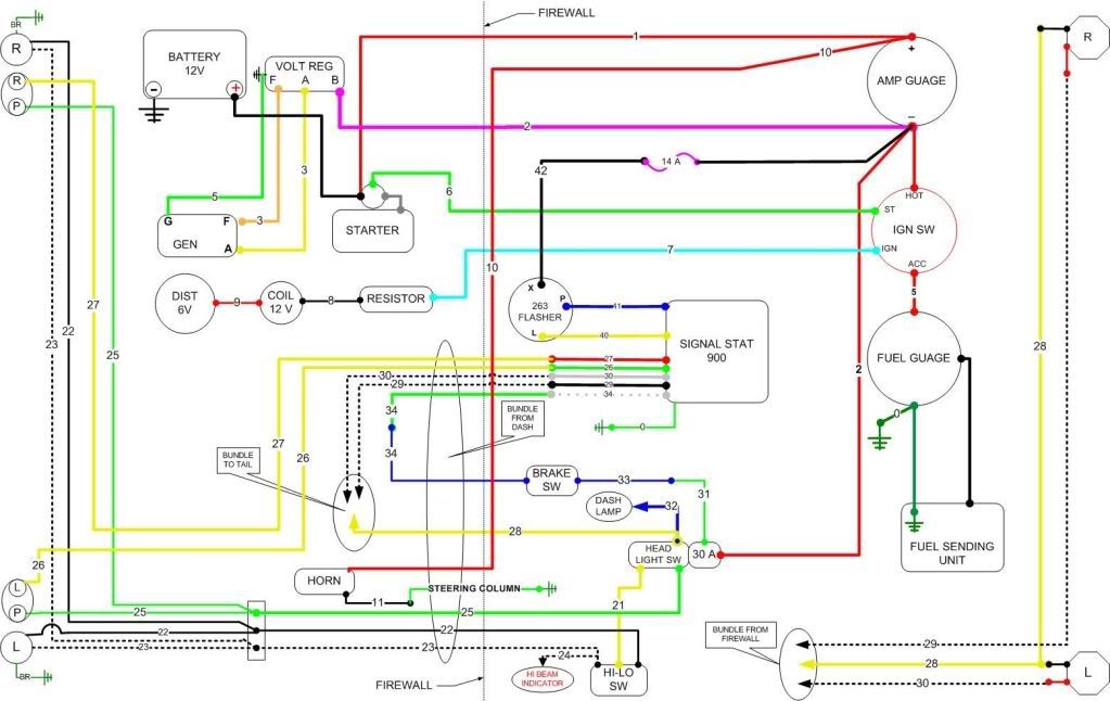
It looks to me like there is a couple things going on here, the battery  is 12v so this is a conversion wiring diagram, distributor is 6volts, coil 12 volts in the diagram.  A 12 volt coil actually runs on 8 volts, so you do have to drop your battery voltage down or it will overheat the coil and burn it out. Like mine did.  I would go to NAPA and ask for a 12 volt coil with a built in resistor, this will eliminate the resistor in your diagram and make your coil and distributor safe at the higher voltage.  

Your other option is to go with a 6 volt battery, then you can drop the resistor from the wiring completely, you will have to make sure you have a 6 volt coil if you do that.
Good luck and keep jeepin
Gun
Posted by: BMIC
« on: February 19, 2013, 10:03:10 AM »

Thanks John, I would love to take credit for it but I dug it up on the 2A page somewhere. Between the two pages you can find anything if you dig deep enough. I might add the Vernco site, great piece on polorizing the system.
Posted by: johnrb3b
« on: February 19, 2013, 09:17:22 AM »

Nice wiring diagram. Did you do it or did it come with a wiring harness?
I'm thinking you did it.
If so, nice job.
Posted by: BMIC
« on: February 19, 2013, 05:12:20 AM »

Thanks Bill/Bob W, my coil does not require a resistor. Bill no fusable link in the wire as I am wiring a temporary dash for a engine test (and hopfully a short run) on the chassis.
Posted by: Bob W
« on: February 18, 2013, 04:40:08 PM »

If your coil requires a ballast resistor just type "chrysler ballast resistor" into your favorite search engine and you will have plenty of info.

Posted by: F Bill
« on: February 18, 2013, 02:32:55 PM »

Check your coil, see if it is marked "for use with resistor" or "no resistor required".....

ALso take a close look at the wire in question and make sure somen hasn't wired in a fusible link or resistor wire.. Fusible links are normallyh marked as such, and the wire in a resistor wire is usually silver colored.
Posted by: BMIC
« on: February 18, 2013, 02:08:26 PM »

Between the coil and ignition switch in my wire diagram is a resistor. Do not remember seeing on on the tear down. Can anyone help me with size and type? � � � � � �